|
Product Information
Rack & Pinion Design
ISO 5211 Drilling
Namur Standards
Travel Stop Adjustment 5° +/-
 Click Here for a downloadable and/or printable version of this page. Click Here for a downloadable and/or printable version of this page. |
 |
|
|
|
|
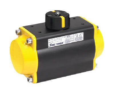
- Rack & pinion design.
- The standard actuator configuration has hard anodized aluminum body and epoxy coated end caps. External protection; resistance to corrosion of 500 hours in a salty atmosphere, according to ASTM B 117-73.
- Inside surface finish (Ra 0.4-0.6 um) to minimize friction and to maximize the life ot the actuator.
- Standard applications for temperature ranges from -4°F to +180°F.
- Special options for extreme temperatures (upon request). Low Temperature Actuator -40°F to 80°F, High Temperature Actuator +5°F to 300°F.
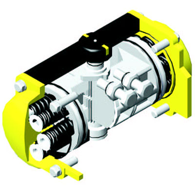
- Piston bearing made of material with low friction coefficient to avoid metal to metal contact, easily replaceable tor maintenance.
- Double lower drilling, for valve mounting, and centering, according to ISO 5211/DIN 3337 standards.
- The indicator is designed to remain on the actuator for continuous indication when limit switch is being used. (Not availabie in SPN 032.)
- Independent bi-directional travel stop adjustment +/- 5° ensuring precise positioning in oil flow control services. (Not available in SPN 032.)
- Direct mounted solenoid connections according to NAMUR standards.
- Same body and end caps for double acting and spring return.
- Air supply: can be dry or lubricated filtered compressed air; pressure: min. 40 PSI- 145 PSI.
- The lubrication carried out by the manufacturer qualifies minimum 1,000,000 operations.
- Epoxy-coating is a deposit of powders on clean and sandblasted pieces. The chemical process is easily kept under control and after coating, the pieces must be subjected to heat treatment. Epoxy painting of actuators is advised where environment is strongly aggressive. With a normal thickness of 200/250 microns of epoxy coating, resistance to salty fog exceeds 1,000 hours. With the exception of certain solvents, epoxy coating resists acids and alkali, and also has a good resistance to UV rays. In order to retain its properties, the coating must not be scratched.
- Multi-function position indicator with NAMUR slot to allow visual position indicator.
|
|
|
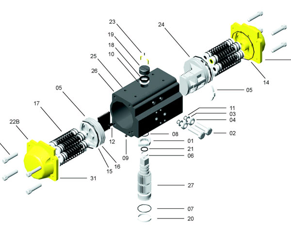
PART
NO. |
QTY. |
PART
DESCRIPTION |
STANDARD
MATERIAL |
| 01 |
1 |
STROKE ADJUSTMENT STOP |
Alloy Steel HT200 |
| 02 |
2 |
STOP BOLT |
Stainless Steel |
| 03 |
2 |
WASHER |
Stainless Steel |
| 04 |
2 |
STOP NUT |
Stainless Steel |
| 05* | 2 | BEARING (Piston back) | Polyphthalamide |
| 06* | 1 | BEARING (Pinion top) | Nylon |
| 07* | 1 | BEARING (Pinion bottom) | Nylon |
| 08* | 2 | THRUST BEARING (Pinion) | Polyphthalamide |
| 09* | 2 | PLUG | NBR Optional: Viton, Silicon |
| 10 | 1 | THRUST WASHER (Pinion) | Stainless Steel 304 |
| 11* | 2 | “O” RING (Stop nut) | NBR Optional: Viton, Silicon |
| 12 | 2 | PISTON GUIDE | Polyphthalamide |
| 13 | 8 | END CAP BOLTS | Stainless Steel 304 |
| 14* | 2 | “O” RING (End cap) | Buna Optional: Viton, Silicon |
| 15* | 2 | BEARING | Polyphthalamide |
| 16* | 2 | “O” RING | NBR Optional: Viton, Silicon |
| 17 | 5-12 | SPRING (Cartridge) | High Alloy Spring Steel |
| 18 | 1 | SNAP RING | High Alloy Spring Steel Optional: Stainless Steel |
| 19 | 1 | POSITION INDICATOR | Polypropylene +GF |
| 20* | 1 | “O” RING (Pinion bottom) | NBR Optional: Viton, Silicon |
| 21* | 1 | “O” RING | NBR Optional: Viton, Silicon |
| 22A | 1 | RIGHT END CAP | Die cast Aluminum Alloy |
| 22B | 1 | left END CAP | Die cast Aluminum Alloy |
| 23 | 1 | INDICATOR BOLT | Stainless Steel 304 |
| 24 | 2 | PISTON | Die cast Aluminum Alloy |
| 25 | 1 | ACTUATOR IDENTIFICATION LABEL | Aluminium |
| 26 | 1 | BODY | Extruded Aluminum Alloy |
| 27 | 1 | DRIVE SHAFT | Steel Alloy Optional: Stainless Steel |
| *Suggested SPARE PARTS For maintenance |
 |
|
|
|
|
|
|
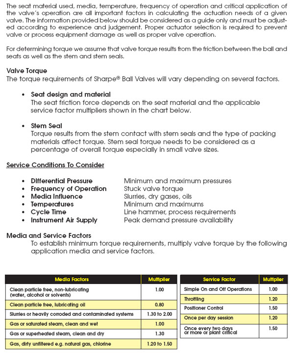
Actuator
Model |
Double
Acting |
Spring
Return |
No. of Springs
Per Side of Piston |
Options |
SPN032
SPN050
SPN063
SPN075
SPN085
SPN100
SPN125
SPN145
SPN160
SPN180
SPN200
SPN240
SPN265
|
DA
|
SR
|
5
6
7
8
9
10
11
12
|
P1 = High Temperature Actuator 300°F
P2 = Low Temperature Actuator -40°F
P3 = Electroless Nickel Treatment
P4 = Epoxy Coating
P5 = 3 Position Actuator
P6 = Actuator Locking Device
P7 = Reverse Rotation
P8 = 180° Actuator
|
|
|
|
Sonic Torque®
Chicago - Headquarters
(708) 409-4150 / Fax (708) 409-4151
E-mail info@sonictorque.com
|


